Product details
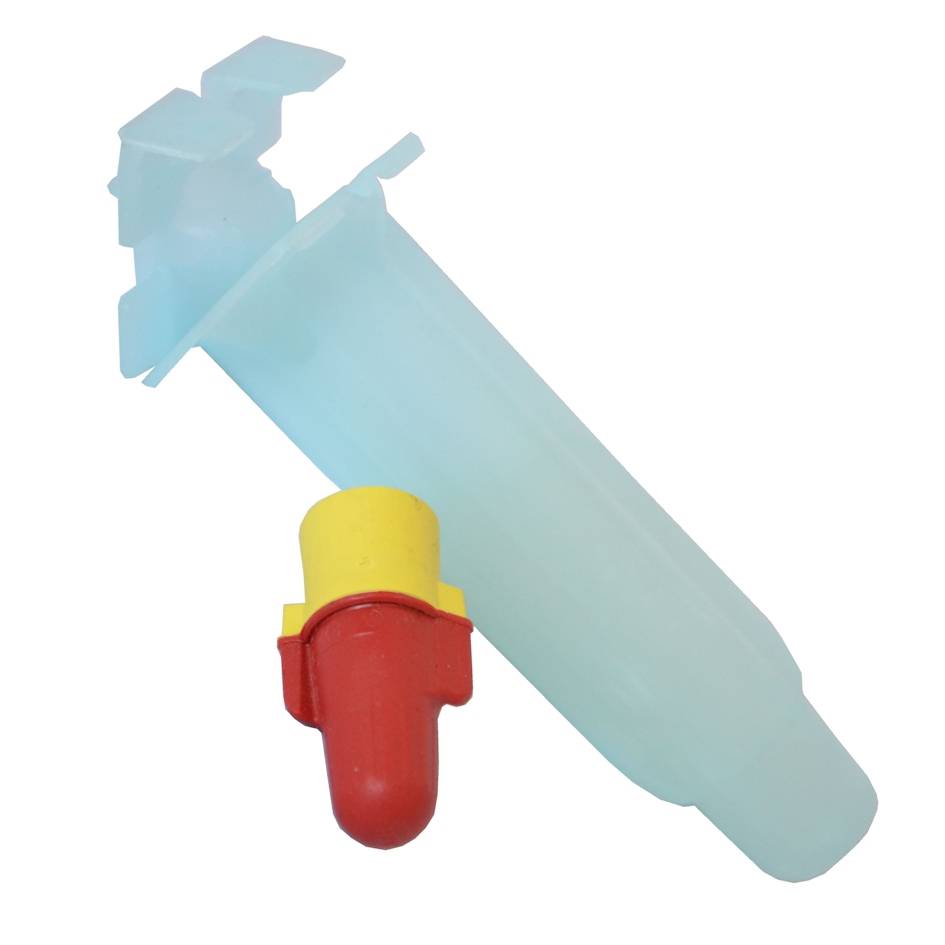
Grease Connector for Decoders are grease filled cable connectors to allows easy connection of cables with grease pot to prevent corrosion. Ideal for decoder irrigation systems which require excellent connections to prevent loss of data. Use with irrigation decoder cable.
Instructions for fitting Grease Connector for Decoders on Hunter DUAL decoders
- Controller power must be OFF when installing decoders in the two-wire path.
Note: Decoder wire runs and connections must be completely waterproof. Decoder wiring is more critical than “conventional” 24 VAC solenoid wiring. Follow instructions closely!
- Select the decoder location (unless you are replacing an existing decoder). Decoders should be within 100 feet/33 m of the solenoids they will operate. Decoders are waterproof, but should be installed in a valve box to facilitate future service and increase longevity.
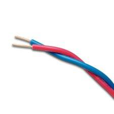
- Locate the two-wire path. These are the red and blue wires coming from the controller. The wire path must be cut to insert decoder wiring, unless you are replacing an existing decoder.
Note: Be sure to leave enough slack in the wire path to allow easy connection of the decoder and to allow for contraction of wiring due to temperature changes. Hunter recommends at least 5 feet/1.5 m slack for each decoder to allow it to be removed from the valve box completely for installation, service, and inspection.

- Identify the color-coded wires on the decoder. The red and blue wires connect to the red and blue wire path from the controller.
- Strip the cut red and blue wire ends back approximately 3⁄4 inch (2 cm).

- Twist the stripped red wire ends (the ends from the two-wire path and the decoder) together, and thread securely into the wire nut supplied with the decoder. Seal the connection by inserting the wire nut into the connector’s waterproof grease until it snaps into place, and snap cap securely over wires.
- Repeat with the blue wires: Connect the blue end(s) from the two-wire path with the blue wire from the decoder, and secure in a separate waterproof connector supplied with the decoder.
- Each pair color-coded decoder output wires operates one or two solenoids up to 100 feet/33 m away (greater distances are possible, but increase susceptibility to lightning damage).
- Strip the insulation and connect the two black wires from the decoder to the solenoid leads for the first station output. If a two-station decoder is being installed, strip back and connect the two yellow wires to the solenoid leads for the second station output. Insert and seal connections with DBY or equivalent waterproof connectors.
- Always terminate each wire path with a DUAL-S surge suppression module. Do not leave unconnected stubs of the two-wire path beyond the last decoder. These may affect the current readings and cause incorrect fault messages.
Grease Connector for Decoders
Grease connector for 2.5mm cable
From: £4.70 (excl VAT)
From: £5.64 (inc VAT)
Code: ELCGD